The Mustangs below are listed alphabeti-cally by name. If you want to search by registry, use ctrl+F...
Here you can find the tales and background information of todays airworthy P-51 Mustangs. Names such as Cripes A' Mighty 3rd, Big Beautifull Doll, Gentlemen Jim, Janie, etc. grace the side of immaculately restored P-51s. More and more companies are getting involved in warbird restoration and the P-51 Mustang remains one of the most popular airframes to rebuild. Approximately 157 Mustangs are airworthy to date, with more than 50 still undergoing restoration to airworthy status.
The North American P-51 Mustang was one of the most widely produced wartime fighter aircraft. After its operational service, a lot of airframes were dumped for sale to the surplus market. Several aircraft were reconditioned and sold to foreign air arms around the world. They provide the biggest share of today's surviving Mustangs. The Royal Canadian Air Force, the Royal New Zealand Air Force and Australia (which produced licence built Mustangs, known as Commonwealth Aircraft Corporation or CAC) account for the part of recovered and restored airframes. When the Royal Canadian Air Force put their Mustangs up for disposal, 87 aircraft were sold to civilian owners, 30 of which still fly today. Of the CAC, 12 aircraft are still airworthy today.
Another major factor in the availability of Mustang airframes was the civilian rebuild of several Mustangs in the late 1960s, early 1970s by the Cavalier Aircraft Corporation.
Several recoveries of Mustang airframes were made in countries such as Nicaragua (12 Mustangs), Guatemala (10 Mustangs), El Salvador (10 Mustangs), Israel (4 Mustangs), Brazil (4 Mustangs) and Indonesia (15 Mustangs). The Dominican Republic used P-51s in operational service for the longest time and was the last country to provide a great number of airframes. On May 19th, 1984, after months of negotiations and bidding, Brian O'Farrell and Armin Mattli acquired the entire Mustang stock of the Fuerza Aerea Dominicana (FAB), including several warehouses full of spare parts (some were even still in their original NAA boxes).
On the left you can find a list of surviving P-51 Mustang airframes still flying today (the list is continuously being updated as a lot of Mustangs are changing hands and several are still undergoing restoration). The list is divided into two sections: on the left they are sorted alphabetically by their civil registration under which they are flying today, together with their paint scheme name. On the right they are sorted by their original serial number.
For each Mustang I've tried to include the history of both the airframe and the paintscheme, pictures and close-ups, as well as serial number, construction number and the current operator.
Be sure to check out Curtis Fowles' amazing site for amazing information on the P-51 and surviving airframes!
Mustangs forever!
As the years progress, more and more Mustang restorers are raising the bar for most authentic restoration.
One of the pioneers in this authentic restoration work is Michael Vadeboncoeur of Midwest Aero Restorations who turned out such amazing restorations as Lil' Margaret, Cripes A' Mighty, Daddy's Girl, and raised the bar with the restoration of Happy Jack's Go Buggy.
Another great and authentic Mustang restoration is that of Aircorps Avation with such amazing restorations as P-51C Lope's Hope 3rd and P-51 Sierra Sue II.
A great amount of work, besides the actual restoration, is getting the paintscheme accurate. This not only concerns the Fighter Group/Squadron markings, but also NAA authentic stencilling and the USAAF mandatory markings.
A quick explanation of some of those USAAF markings of Mustangs in WWII can be found below.
Olive Drab Mustangs
Quick Identification Markings (QIM)
Unit Letters & Aircraft Call Letter
Radio Call Numbers
To avoid being mistaken for Me-109s because of square cut wings an issue was ordered on February 20th , 1943.
White bandings were to be applied around the nose, tail surfaces and wings, more specifically:
Unit letters were to be painted in white 24-inch high block capitals, and placed forward of the national insignia on both sides of the fuselage.
The individual plane-in-squadron letter was usually placed aft of the national insignia. A bar was added below the aircraft's call-letter if that aircraft was the second within their respective unit to carry a duplicate call-letter.
This bar was displayed on both the ships' fuselage as well as tail call-letter locations. This was often the case when aircraft numbers within a squadron exceeded the total of 26.
Radio call numbers replaced aircraft designators starting in August of 1941.
These were to be painted on the vertical tail surfaces, on both sides of the aircraft.
Shortly after the revised April 8, 1941, issue of T.O. 07-1-1 came out, the Air Corps Inspection Division recommended that the specified airplane designators should be replaced by the airplane radio call (i.e. the aircraft serial number). It was suggested that this should be painted in large figures in a conspicuous place on the airplane, such as on the fin or the side of the fuselage. Meanwhile, the Training and Operations Division had also recommended that the number should be painted on the vertical fin at the factory, as this would be easy and the number would also serve as the manufacturer's identification.
Both of these recommendations were approved by the Chief of the USAAF in a teletype to Maintenance Command on August 22, 1941.
The radio call number was made up of the last digit of the fiscal year of procurement, followed by the Army Air Force serial number.
For example, Boeing B-17E, serial number 41-2393 would have the radio call number 12393 painted on the vertical tail.
Another change was that the new designator was to be painted on by the manufacturer at the factory, whereas previously, airplane designators had been painted on by the service units concerned.
Each Army Air Force airplane (including training types), regardless of whether equipped with radio, was to be identified. The call numerals composing the airplane designator were to be of the vertical block type, the width two-thirds of the height and the strokes approximately one inch (2.54 cm) wide for every six inches (15.24 cm) of height. The distance between the letters was to be equal to half the width of a letter.
Due to the varied sizes and configurations of Army Air Force airplanes, it was impractical to specify a standard height of letters that would meet the requirements for all airplanes. In general, the height of the numerals was such as to make the designator readily discernible from a distance of approximately 150 yards (137 m). The numerals comprising the designator were to appear in one line painted in a centrally located position.
For airplanes not camouflaged, the designator was to be on each side of the vertical stabilizer. If there was more than one vertical stabilizer, the designator was to appear on the left exposed side of the left-hand stabilizer and on the right exposed side of the right-hand stabilizer.
On camouflaged airplanes, the designator was to be the same as above, except that the necessary area of both the vertical stabilizer and the rudder was to be utilized. If there was insufficient area on the vertical stabilizer or on the vertical stabilizer and rudder combined, the numerals could be placed on the sides of the fuselage.
Black numerals were to be used against a light background - in the case of camouflaged airplanes, black Shade 44 of Bulletin No. 41.
Yellow was to be used against a dark background, A-N orange-yellow for uncamouflaged airplanes or Identification Yellow, shade 48 of Bulletin No. 41, for camouflaged airplanes.
Natural Metal Mustangs
Gen. Arnold signs order eliminating camouflage on all aircraft, October 30, 1943:
On October 30, 1943, the Prod. Eng. Sect. (WF), informed by teletype the Western Procurement District, Los Angeles, CA, that Lt. Gen. B. Giles, C/As (Wash.), had signed an order, which had been counter-signed by Gen. Arnold and Lt. Gen. Carl Spaatz (Northwest African Air Force), eliminating camouflage from all aircraft. WF had not then officially received the order, but suggested that the District withhold for one week, approval of any funds for paint buildings.
Camouflage no longer required for any AAF aircraft except night fighters, November 1943.
On November 3, 1943, HQ. AAF sent the following message to the VIII Air Force Service Command:
Approved policy on camouflage is quoted in substance as follows: “No requirement exists for camouflaging any AAF aircraft except Night Fighters.
Night Fighters shall be painted with non reflecting type camouflage paint.
Camouflage paint will be eliminated from all production AAF airplanes subsequently produced except Night Fighters.
Navy type aircraft will be accepted with Navy camouflage.
Camouflage may be removed from existing AAF airplanes at the option of the Theater Commander or Commanding General under whose jurisdiction such aircraft operate in accordance with technical instructions issued by Commanding General Air Service Command.
Future production aircraft which require painting such as fabricated of wood shall be painted with aluminated paint”.
Above policy in no way prohibits Theater Commander if he desires from (retaining-sic) aircraft camouflage.
Quick Identification Markings (QIM)
These were identical to the ones applied to the camouflages Mustangs, except that they were painted in black instead of white.


Unit Letters & Aircraft Call Letter
Radio Call Numbers
Again, these were identical to the ones applied to camouflage Mustangs, except that they were painted in black instead of white.
The radio call numbers were applied in exactly the same way as on camouflage Mustangs, except that they were applied in black.
Radio call number color changed, March 1944.
Spec.98-24105-R, amendment no. 2, dated March 21,1944, revised some of the color requirements for the radio call numbers. The new requirements read as follows:
Uncamouflaged airplanes. - For light colored backgrounds, the numbers shall be black, and for dark backgrounds, the numbers shall be International Orange, in accordance with color shade No. 508, Bulletin No. 166.
Camouflaged airplanes. - For light colored backgrounds, the numbers shall be black in accordance with color shade No. 604 of Bulletin No. 157, and for dark backgrounds, the numbers shall be Orange Yellow, in accordance with color shade No. 614 of Bulletin No. 157, except that the numbers for night fighter aircraft shall be Insignia Red in accordance with color shade No. 619 of Bulletin No. 157.
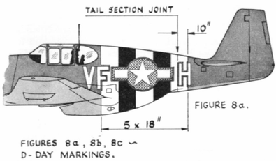
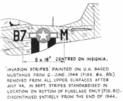
Officially known as Allied Expeditionary Air Forces Special Markings (or Invasion Stripes), these alternating series of black and white stripes were by Supreme Headquarters Allied Expeditionary Forces (SHAEF) in early 1944 by means of a top secret Operation Memorandum Number 23, entitled “DISTINCTIVE MARKING – AIRCRAFT” (the complete text of this document can be found below).
This order was issue to all USAAF and RAF aircraft units in anticipation that the German Luftwaffe would respond in great strength during Operation Overlord (D-Day landings). There was a profound fear that allied aircraft would be mistaken for the enemy by the Allied ground troups, Navy and Air Force. Experience during the landings in Sicily learned that this kind of distinctive markings greatly reduced the number of so-called “friendly-fire accidents”.
The order was effective 11am. Sunday, June 4th , 1944, and stated that no aircraft were to fly without the new markings.
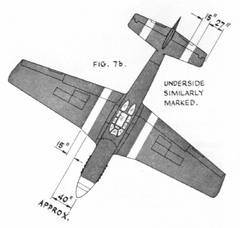
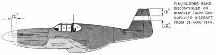
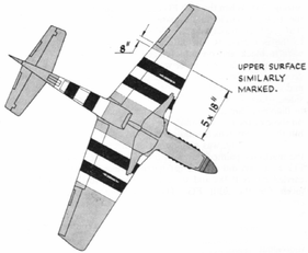
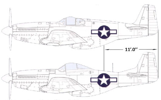
The markings consisted of five alternating 18-inch wide stripes (white/black/white/black/white) around the rear fuselage and around each wing. The stripes on the wings were to be 15 inches wide.
On the wing, the outer white stripe was to be 6 inches from the national insignia. On the fuselage, the edge of the rearmost stripe was to be 18 inches from the leading edge of the tailplane, but the stripes should in no case obscure the national marking.
The outer white stripes obliterated most of the individual aircraft letter and the second letter of the squadron code. In some cases they were painted around and in others reinstated.
After invasion, the stripes were found to compromise camouflage .On July 6th, 1944 The U.S. 8th Air Force started removing upper stripes followed by many other units though no order from SHAEF has been found.
On August 1st, 1944 amendment 3 (to operational memorandum 23) ordered all wing stripes removed from August 25th onwards. Fuselage stripes were to remain intact. Many units removed the upper fuselage stripes at this time in a "liberal" interpretation of the order (the text of this amendment can be found here). This meant that the stripes now disappeared from the top half of the wings and fuselage).
In December, the remaining portion of the markings on the underside was to be deleted by the last day of the year.
Supreme Headquarters Allied Expeditionary Force issues Top Secret memo whose subject was "Distinctive Marking. Aircraft", dated April 18th, 1944 (the "Invasion Stripes").
On April 13th, 1944, the newly formed Supreme Headquarters Allied Expeditionary Force issued a draft of a major Operation Memorandum, Number 23, entitled "DISTINCTIVE MARKING - AIRCRAFT". This was approved very quickly and issued on April 18th, 1944.
Only 100 copies of the Top Secret document were made; 55 were issued to the necessary commands, each bearing its own number. The other 45 copies were held as spares. The following information comes from copy number 36, issued to the Chief Administrative Officer.
TOP SECRET
SUPREME HEADQUARTERS
ALLIED EXPIDITIONARY FORCE
OPERATION MEMORANDUM
NUMBER 23
TOP SECRET
Copy No. 38
18 April, 1944
DISTINCTIVE MARKING – AIRCRAFT
1. OBJECT
The object of this memorandum is to prescribe the distinctive markings which will be applied to US and BRITISH aircraft in order to make them more easily identified as friendly by ground and naval forces and by other friendly aircraft.
2. SCOPE
a. The instructions contained herein will apply to the following types of US and BRITISH aircraft: (I) Fighters and fighter bombers. (2) Tactical and photographic reconnaissance aircraft. (3) Aircraft employed in spotting for naval gunfire and field artillery. (4) Light bombers. (5) Medium bombers. (6) Troop carrier aircraft, including four engine types. (7) Glider tugs, including four engine types. (8) Liaison aircraft and Air OP's employed in forward areas for fire spotting and adjustment or for advanced aircraft control. (9) Coastal Command, Air Sea Rescue and disembarked Fleet Air Arm aircraft except seaplanes and four engine aircraft which need not be marked.
b. These instructions will not apply to the following classes of aircraft:(l) Four engine bombers. (2) Air transports. (3) Gliders. (4) Night fighters. (5) Seaplanes.
3. GENERAL
a. The instructions contained herein will be effective on the day of the assault and thereafter until it is deemed advisable to change. Aircraft will be given distinctive markings as shortly before the day of the assault as it is possible in order to protect the effectiveness of their use.
b. These instructions are in no way intended to change the present US and BRITISH national markings now in use, namely: the USAAF white star on a white horizontal bar; and the RAF red, white and blue roundel.
4. DISTINCTIVE MARKINGS
a Single engine aircraft. (I) Upper and lower wing surfaces of aircraft listed in paragraph 2 g above, will be painted with five white and black stripes, each eighteen inches wide, parallel to the longitudinal axis of the airplane, arranged in order from center outward; white, black, white, black, white. Stripes will end six inches inboard of the national markings. (2) Fuselages will be painted with five parallel white and black stripes, each eighteen inches wide, completely around the fuselage, with the outside edge of the rearmost band eighteen inches from the leading edge of the tailplane.
b. Twin engine aircraft. (I) Upper and lower wing surfaces of aircraft listed in paragraph 2 g above, will be painted from the engine nacelles outward with five white and black stripes, each twenty-four inches wide, arranged in order from center outward: white, black, white, black, white. (2) Fuselages will be painted with five parallel white and black stripes, each twenty-four inches wide, completely around the fuselage, with the outside edge of the rearmost band eighteen inches from the leading edge of the tailplane.
c. Four engine troop carrier aircraft and g lider tugs. (I) Same as for twin-engine aircraft, wing stripes to be outboard of the outer engine nacelles.
d. Stripes will in no case be painted over the national markings, which take precedence. Wing stripes will extend from leading edge to trailing edge of wings. Special equipment, such as deicer boots, will not be painted over.
e. Types of paint to be employed: (1) USAAF Units - as directed by the Commanding General of the Air Force concerned. (2) RAF Units - as directed by the appropriate BRITISH agency.
f. At Appendix' A: are sample sketches of aircraft painted according to these instructions.
5. BRIEFING
Army, Navy and Air Commanders will disseminate complete information concerning these distinctive markings to all troops under their commands no earlier before the day of the assault than will insure the complete distribution of the information.
By command of General Eisenhower:
W. B. Smith
Lieutenant General, U.S. Army,
OFFICIAL: Chief of Staff.
H. R. BULL,
Major General, G.S.C.,
Assistant Chief of Staff, G-3.
Final action on SHAEF Operation Memorandum Number 23 came the next day, December 6th, 1944, when SHAEF released the following document:
This is the First Suspension/Cancellation of a SHAEF OPERATION MEMORANDUM.
SUSPENSION OF OPERATION MEMORANDUM NUMBER 23, 6th December, 1944
DISTINCTIVE MARKINGS - AIRCRAFT
1. The provisions of Supreme Headquarters, AEF, Operation Memorandum No.23, Distinctive Markings - Aircraft, are suspended effective December 31st, 1944.
2. Except as noted in sub-paragraph 44. below, distinctive markings will be removed where this can be done without damage to the aircraft and with due regard to the materials and time available for this work.
3. Addressees will ensure complete dissemination of the pertinent provisions of this suspension by the quickest possible means consistent with security.
4. All Commanders will particularly ensure that personnel under their command are instructed that:
a. The fact that an aircraft of allied manufacture is seen without distinctive markings does NOT necessarily indicate that the aircraft is hostile. b. For some time Allied aircraft may still be seen carrying distinctive markings, which, with the exception of those in sub-paragraph 4 below, should now be disregarded.
c. Faded striping under certain conditions of light closely resembles the German cross.
d. For the purposes of facilitating identification by other friendly aircraft all of the photo reconnaissance aircraft of Number 34 Wing, Second Tactical Air Force will be painted with standard invasion markings until such time as all recipients of this instruction are notified by Air Officer Commanding-in-Chief, Second Tactical Air Force.
5. The removal of these distinctive markings in no way affects the presently prescribed national markings, which will continue to be carried on aircraft.
6.In future, should there be a requirement for distinctive markings, application will be made to this Headquarters.
By Command of General EISENHOWER.
On August 1st, 1944, ANCXF (Allied Naval Commander Expeditionary Forces) responded to the SHAEF proposal with the following signal:
Yours 302025. Proposal to retain fuselage markings only concurred in but consider this should continue to apply to all classes of aircraft as in your memorandum number 23. Markings have proved valuable to Naval Forces where operations are not confined to Assault Area and to remove them from some classes of aircraft will cause doubt.
If it is decided to remove wing markings concede that this should be done in as short a time as possible and all concerned then informed.
Somewhat later, on August 7th, 1944, HQ Twelfth Army Group (signed Bradley), sent SHAEF Forward the following signal:
Reference SHGCT dated 30 July 1944. This Headquarters concurs in the proposed change of distinctive aircraft markings as contained therein.
Change No.4 to the Op. Memo No. 13, dated October 13,1944 ordered the removal of all stripes on Allied aircraft, but on October 25, 1944, a TWX from USSTAF to the various fighter commands stated that:
The present method of applying distinctive markings on your fighters authorized by SHAEF. By this authority you are authorized to disregard instructions contained in change no. 4 to Operations Memorandum No. 13 (29 April 1944) of HQ ETOUSA dated 13 October 1944.
Distinctive Markings on single and twin engined aircraft will be as follows:
(A) The under, repeat, under surface of fuselages of single engined aircraft will be painted with five (5) parallel white and black stripes, each eighteen (18) inches wide, with the outside edge of the rearmost band eighteen (18) inches from the leading edge of the tailplane.
(B) The under, repeat, under surface of twin engined aircraft will be painted with five (5) parallel white and black stripes, each twenty-four (24) inches wide, with the outside edge of the rearmost band eighteen (18) inches from the leading edge of the tailplane.
This meant that the stripes now disappeared from the top of the wings and fuselages of all fighter type aircraft.
The US National Insignia also underwent a couple of modifications throughout the early career of the USAAF/USAF. Below are the changes made on USAAF aicraft starting in 1940, untill the end of WWII:


Within 6 months of Pearl Harbor, both the tail markings and the US Army letter designation were dropped. The National insignia was directed to be applied on both sides of the fuselage for the first time. At the same time, the insignia was ordered removed from the top right and lower left wing tips, as opposed to both top and bottom on both wings before.
(it was thought this was a convenient aiming point for the enemy).
First major change in 25 years to the “Star-in-Circle” design. The red inner circle device was ordered removed to reduce possible confusion with the Japanese Hinomary (Meatball) insignia.
T.O. 07-1*1 Amended to add Medium Green patches to wings and revises insignia requirements, July 10,1942.
T.O. 07-1-1 was amended to include a new paragraph l.f. (1) (c) and revised paras. 5.a. and 6.
l.f. Use of Special Color of Camouflage Materials.
(1) The basic camouflage scheme in permanent camouflage materials for AAF aircraft is as follows:
(c) Medium Green, Shade No.42 in splotches or patches along the leading edges, tips and trailing edges of the wing, vertical and horizontal stabilizers and rudders.
1. Application should be made so that the continuity in appearance of the wing, stabilizer, and rudder outlines
is broken.
2. The size of the splotches or stripes should extend inward from the edges at various distances ranging fro 0
to 20% of the width of wing, stabilizer or rudder member.
5. Markings.
a. The markings for all military aircraft will be in accordance with Spec. 98-24105 (airplanes), or 99-2050 (lightcr-
than-aircraft) except that on camouflaged aircraft the marking “U. S. Army” on the under surface of wing will be omitted.
6. Standard Insignia. Standard military insignia will be placed and maintained on each aircraft as outlined in Spec. 98-24102, or Spec. 24114 (airplane camouflage) which includes the following:
a. The red circle in the middle of the star insignia as used as present will be eliminated on all types of aircraft. The new
type of insignia will therefore be a five pointed, white star within a blue circle.
b. All rudder stripes will be eliminated and the color of the rudder will be the same as that of the upper surfaces of the
fuselage except as noted in para, l.f.(l) (e).

A 2-inch yellow border surrounding the National insignia was used on aircraft serving in both Great Britain and North Africa.
Yellow outer ring added to lower wing and fuselage insignia for aircraft destined for use in invasion of North Africa, in Amendment to Op. Memo No. 9 for operation “Torch,” dated September 30, 1942.
In preparation for Operation “Torch”, the Allied invasion of French North Africa, an amendment dated September 30, 1942, to Operation Memorandum No. 9, dated September 25, 1942, was issued by Allied Force Headquarters under Gen. Eisenhower’s command. This amendment added a yellow ring around the star insignia on the fuselage and under the wing of all American aircraft taking part in this invasion. Intended for ground recognition, it was not required for use on the upper wing insignia
A revised version of T. O. 07-1-1 was issued on June 15, 1943, containing color chips and color views of the various official camouflage schemes at that time. Part of the order:
T. O. NO. 07-1-1 JUNE 15, 1943.
AIRCRAFT
CAMOUFLAGE
MARKINGS AND INSIGNIA
This Technical Order replaces T. O. Nos. 07-1-1, dated June 1, 1943,
07-1-lA dated January 9 1943 and 07-1-IB dated August 15 1942.
Note: The work directed herein will he accomplished whenever
necessary by service activities with the aid of sub-depots if necessary.
...
SECTION II
MARKINGS AND INSIGNIA
3. MARKINGS
a. Each part and assembly will be permanently and legibly marked the same number as the drawing number in
such location that it can be read after assembly in the unit. (See Specification No. 98-241050.)
b. Various detail and code markings for the cockpit, fuselage, oil lines, etc., as required in Specification No. 98-241050, will be maintained.
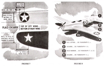
c. Radio call letters of not less than four numbers, utilizing both sides or each outboard side, as applicable, of
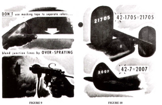
vertical stabilizer and rudder assembly, will be maintained on all Army Air Forces aircraft. (See figures 8 and 10.) Call letters, or designators, will be derived by deletion of the first numeral of serial number (4) and the hyphen, and the combination of the remaining four or more numerals. In case of serial numbers of type 41-7, use zero as necessary to make four numerals, as 1007. Dccalcomanias may be used in all cases where available. Standard sizes 8 x 12 inches and 6x9 inches may be used when present stocks are depleted. Colors will be yellow, shade No. 48, for dark camou flage, and black, shade No. 44, for light surfaces.
d. Under no condition will the letters “U. S. Army” be applied to any airplane lower wing surface.
4. STANDARD INSIGNIA.
Cocardes, the five-point white star within a blue circle, will be placed and maintained on each Army Air
Forces aircraft as indicated in the following paragraphs. Decalcomanias will be used in all cases where available
WARNING
Under no condition will the red circle within the white star be used.
a. WINGS.—Insignia of a size 80 to 90 percent of available width of wing at location specified herein will be
maintained on top surface of left wing and lower surface of right wing with point forward. The center will be located inboard from each wing tip one-sixteenth of the total wing span on wings not tapered, but with outside edge not nearer than 6 inches to end, and one-eighth of span on tapered wing. The cocarde will be located tangent to the aileron cut out or midway of the wing width on those on which aileron cut-out is not a factor. (See figures 7 and 8.)
b. FUSELAGE.—One star insignia approximately 75 percent of height of fuselage will be applied to each
side with point upward near-midway between the trailing edge of the wing and the leading edge of the horizontal stabilizer. (See figure 8.)
c. RUDDER STRIPES.—The use of rudder stripes is prohibited
....


During combat over North Africa in support of Operation TORCH, it was found that the AAF star insignia was being confused with the Luftwaffe cross at distances exceeding normal resolution (this had also happened during World War I, and led to the adoption of the tri circle insignia for all AEF aircraft in France).
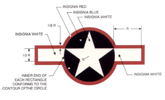
This was the second major change in the National Insignia, namely the birth of the “Stars ‘n Bars”. A white rectangle or bar was added on each side of the blue circle with a red border surrounding the entire insigne. While the new design was estimated to be 60 percent more recognizable, the use of the red border was short lived.
Specifications:
Another brief variant in the ETO was the addition of yellow inner bars.
On June 15, 1943, Eglin Field, was directed to conduct tests on modifying the AAF insignia so that it would not be confused with enemy insignia at distances exceeding normal resolution.
As it so happened, tests had already been conducted earlier and had been reported in Service Test No. 3-42-18, “Revision of Aircraft Marking”, dated May 9, 1943. These tests had been run to determine the cause of the confusion at distances (the results agreed with those reported in McCook Field Report No. 1305, dated August 20,1920, showing that at a distance the white star of the insignia blended into a circular blob).
The tests had shown that a long narrow rectangle added to the star insignia proved to be discernible at a distance twenty-five percent farther than the Luftwaffe cross or the AAF star insignia.
T. O. 07-1 -IB, issued on June 29,1943, orders immediate use of the new insignia.
The same day that the revised version of AN-19a introduced the new rectangular bar insignia, HO. AAF issued a revision to T. O. 07-1- 1, which stated that:
The work directed herein will be accomplished immediately by service activities with the aid of sub-depots, if necessary.
Under para. 4. STANDARD INSIGNIA., it stated:
a. A cocarde of new design as described below will be placed on all aircraft of the AAF immediately. (Refer to figure 11.)
(1) A five pointed white star within a blue circle (as formerly).
(2) The straight line formed by the top edges of the two star points which are located to the left and right respectively
of the upper star point, will be extended outward a distance equal to 1 radius of the circle on either side. Draw lines perpendicu lar to this line at each end and extending downward for a distance equal to 1/2 the radius of the circle. Draw lines parallel to the above horizontal line from the ends of the two perpendicular lines until they intersect the circle. The bars thus created will be painted white.
(3) Using a width which is 1/8 the radius of the circle, describe a border of red around the entire design outlined in
paragraphs 4.a.(l) and (2).
At the end of this section of the T. O., the following was added:
NOTE: Existing insignia may be reworked by adding the white rectangular areas and the red border provided that the provisions of paragraphs 4.b. and c. are complied with in so doing.
T. O. 07-1-1C fixes diameter of the new wing insignia, July 3,1943
A few days after the new insignia was issued, a change was made to the wing insignia size. The new order read : “Diameter of the blue circle will be 75 percent of the distance between the leading edge of the wing and the aileron cut-out except that the circle will not be greater than 60 nor less than 30 inches in diameter.”
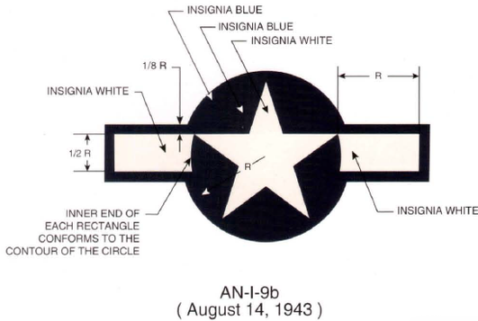
Despite all of the research that had gone into the design of the new red-bordered national insignia, it was soon found necessary to make a further change, making the new outline border Insignia Blue, rather than Insignia Red.
This change resulted primarily from combat units in the Pacific theater still confusing the red in the insignia with the Japanese insignia. Thus, although various new orders directed the change to be made as soon as possible, in actual fact the change was made much more expeditiously in the Pacific theater than in the European theater. In Europe, aircraft could still be seen with the red-bordered insignia at the end of 1943
AN-I-9b included other lesser changes, which also had many long-term effects. These included deleting the word “star” from the name of the national insignia. For night fighters, size of the wing insignia circle was to be 25 inches in diameter, and the fuselage circle was to have a minimum diameter of 20 inches (as before) and a maximum diameter of 25 inches. On all aircraft, the fuselage insignia could extend over doors and emergency exits, but could not extend over windows or such openings used during combat which would change the insignia pattern.
T. 0.07-1-1D changes National Insignia outline border color to Insignia Blue, September 24,1943, to agree with the new issue of AN-I-9b.
The National Insignia was revised in T. O. 07-1-1D, to require the use of a BLUE BORDER in lieu of the RED BORDER formerly specified.
The work was to be accomplished as soon as possible and not later than the next 25-hour inspection by service activities with the aid of sub-depots, if necessary.
The new T. O. changed all previous references to the RED BORDER to one of BLUE. The new insignia was to now consist of a five- point, white star within a blue circle, as previously specified, together with the two white rectangles, this entire design to be circum scribed by a BORDER of BLUE whose width was 1/8 the radius of the original blue circle. Existing insignia could be reworked by painting over the existing red border with insignia blue, shade No. 47.
New version ofT. O. 07-1-1 deletes camouflage, December 26,1943
TECHNICAL ORDER No. 07-1-1 December 26, 1943
DOPES, PAINTS AND RELATED MATERIALS
GENERAL—AIRCRAFT CAMOUFLAGE, MARKINGSAND INSIGNIA
This Technical Order replaces T. O. Nos. 07-1-1, dated June 15, 1943; 07-1-1C, dated
July 3, 1943; and 07-1-1D, dated September 24, 1943.
1. AIRCRAFT CAMOUFLAGE
a. Painting of the exterior metal surface of Army Air Forces aircraft is hereby discontinued, except as may be directed
otherwise by the Commanding General Army Air Forces for aircraft destined for delivery to foreign agencies. This does not, however, eliminate the required identification data, insignia, anti-glare coatings, and corrosion prevention. Man-hours expended on maintaining existing camouflage finishes, now considered unnecessary, will be held to a minimum.
b. Paint may be removed from presently painted metal aircraft by the operating organizations at the discretion of Commanders concerned, as local facilities and materials are available, provided no interruption in operations is entailed. Alumi nized parts installed on a camouflaged aircraft will not be camouflaged. However, when any unpainted metal surface of suffi cient area is installed that would materially affect the flight characteristics of the airplane, the remaining camouflage paint may be removed. Camouflaged metal parts installed on unpainted airplanes need not have camouflage removed.
c. All fabric control surfaces and fabric-covered aircraft will be aluminized when re-covering is necessary.
d. PARTS IN STOCK.
(1) Aircraft airfoils and other exterior metal parts in stock need not have the camouflage paint removed.
(2) Fabric control surfaces in stock, or installed as replacements, need not be refinished for any color match
ing purposes.
e. Camouflage black need not be applied to propellers unless required for antiglare purposes or corrosion resistance;
however, the 4-inch yellow tip must be maintained as a safety measure. Repaired hollow steel blades from which any of the protective plating has been removed will be painted as outlined below, to protect against corrosion. Wood propellers will not be painted black.
(1) If camouflage black is to be used for antiglare or corrosion resistance purposes, it will be accomplished by spraying
the hub and each propeller blade while in a horizontal position, and retaining the propeller in this position until the camouflaging materials have set. Over one light coat of zinc chromate primer, Specification No. AN-TT-P-656, one light coat black cellulose nitrate camouflage lacquer, shade No. 44, will be applied and will extend to within 4 inches of the tip of the blade; this 4-inch tip section will receive one light coat of yellow lacquer, shade No. 48. The propeller will then be checked for balance.
(2) When necessary, three-and four-blade metal propellers may be lightly touched up between overhaul periods, while
installed on the airplanes. Care will be exercised to apply proportionate amounts of paint to each blade to maintain proper blade balance.
2. AUTHORIZED FINISHES.
a. The exterior of metal fuselages and metal airfoils do not ordinarily require paint as a protection against corrosion (T. O. No. 01-1-2). However, where it is necessary to provide additional protective finish on any parts not made from chromium- coated sheet material, any such unprotected parts will be cleaned with phosphoric acid alcohol cleaner, finished with one coat of zinc chromate primer, Specification No. AN-TT-P-656, and two coats of aluminized lacquer. Aluminized lacquer consists of lacquer, cellulose nitrate, clear, Specification No. AN-TT-L-51, pigmented with 12 ounces per gallon of paste, aluminum pig ment, Specification No. TT-A-468.
b. Antiglare camouflage olive drab or dull dark green paint is authorized, where necessary, to be applied to top of the
fuselage in front of the cockpit and on the inside upper one fourth of the engine nacelle.
c. Exterior plywood surfaces will be finished with two coats of sealer, Specification No. AN-S-17, or on open
grained woods, one coat of sealer followed by one coat of surfacer, Specification No. 14115, sanded down, before the final two coats of aluminized varnish. Use 16-20 ounces of pigment, aluminum paste, Specification No. TT-A-468, in each gallon of varnish, Specification No. AN-TT-V-116 or No. AN-TT-V-118.
d. /Ml exterior fabric parts will have a minimum of two brush and two spray coats of clear nitrate dope, Specification No. AN-TT-D-514 (aluminized dope vehicle AN-TT-D-551 is not a suitable substitute, as it does not have the tautening quali ties of AN-TT-D514). This will be followed by two or more coats of aluminized dope prepared by adding 8 ounces per gallon of paste, aluminum pigment, TT-A-468, to dope, cellulose nitrate, clear, Specification No. AN-TT-D551, before thinning.
e. Patching will be accomplished with clear dope. Specification No. AN-TT-D-514, applied in same manner as
semipigmented dope previously used.
f. EMERGENCY REJUVENATOR FOR OLD FABRIC. - To one gallon of two to one mix of clear dope, Specifica
tion No. AN-TT-D-514, and blush retarding thinner, Specification No. AN-TT-T-258, add 1 fluid ounce each of tricrcsyl phos phate and castor oil. Apply one coatby brush to clean surface, followed by one spray coat. After several hours drying, spray one coat aluminized dope, prepared as specified in paragraph 2.d.
g. For removal of all types of paint material from metal surfaces, use paint and varnish remover, Specification No. 14119, for removal. If not available, lacquer finishes may be removed with material compounded by the following formula: 3 gallons benzene, 2 gallons acetone, 1 pound paraffin wax. For removal of dope from fabric surfaces, use nitrate dope and lacquer thinner, Specification No. AN-TT-T-256.
3. MARKINGS.
Only such markings and identifying insignia as outlined herein will be used on AAF aircraft except as specifically
authorized by the Commanding General, Army Air Forces.
a. Each part and assembly will be permanently and legibly marked the same number as the drawing number in such
location, that it can be read after assembly in the unit.(See Specification No. 98-24105.)
b. Various detail and code markings for the cockpit, fuselage, oil lines, etc., as required in Specification No. 98-24105
will be maintained.
c. Radio call numbers of not less than four numbers will be maintained on all AAF aircraft, utilizing both sides or each
outboard side, as applicable, of vertical stabilizer and rudder assembly; on all airplanes operating solely within the continental limits of the United States, the radio call numbers will also be placed on the lower surfaces of both wings. These are not
required, however, on primary trainers not equipped with radio and which bear field identifying numbers. Wing numerals will
be placed with the lop forward on the right wing immediately inboard of the insignia and in a corresponding position on the left wing. Call numbers, or designators, will be of a size discernible at a distance of 150 yards. They will be derived by deletion of
the first number of the serial number (4) and the hyphen, and the combination of the remaining four or more numerals. In case
of serial numbers of type 41-7, use zero as necessary to make four numerals as 1007. Decalcomanias may be used where
available.
d. Under no conditions will the letters “U.S. Army” be applied to any airplane lower wing surface.
e. American propeller blades, design Nos. A-2721107 add C-3821306, used in sets in Aeroproducts and Curtiss propel
lers, respectively, will be identified by a yellow stripe, 3/8 inch in width and 3/8 inch inboard of the yellow tip section. A. O.
Smith propeller blades used in sets in Curtiss propellers will be identified by two 3/8-inch yellow stripes, one 3/8 inch inboard of the yellow tip section and the second stripe 3/8 inch inboard from the first. These stripes will extend completely around the blade section.
CAUTION Care will be exercised to mask any angular graduations on the propeller hub or blades. The space between the blade shank and barrel will be masked-off to prevent paint from contacting the seals.
The stenciled markings between the 18- and 24-inch R stations on the cambered side of the propeller blades will be retained.
f. SPECIAL TRAINER MARKINGS.
(1) Painting of ring cowls is authorized in colors, as directed by the Commanding General of the AAF
Training Command.
(2) Field identification numbers and radio call letters are authorized, as designated by the Commanding Gen
eral of the AAF Training Command for use in Army Air Forces Training Organizations and Civil Flying Schools. They will be
of contrasting color, preferably block type, and will be applied to opposite sides of the fuselage in front of the insignia. The
height will be the greatest practicable for the location required.
(3) Aircraft used only for instrument training may be distinguished, at the discretion of the Commanding
General of each particular Command, as follows, except that such markings will not be applied to first line combat type aircraft:
(a) Rudders and vertical fins painted insignia red.
(b) Insignia red stripes, 18 inches wide, extending from junction of leading edge of wing and fuse lage, diagonally (45 degrees to axis of the plane) to the trailing edge of the wing, top and bottom.
(c) Ring cowls to be painted insignia red.
(d) Multi-engine aircraft nose sections to be painted insignia red from the cockpit forward.
g. Markings and insignia may be made with any of the following materials:
(1) Enamel, Specification No. 14109 or No. ANE-3 (3-98).
(2) Insignia colors in oil, Specification No.3-120.
(3) Lacquer, Specification No. 14105 or No. ANTT-L-51.
(4) Dope, Specification No. 14108 or No. AN-TTD-554.
4. STANDARD INSIGNIA.
a. Standard insignia of the design shown in figure 1, will be placed on all Army Air Forces aircraft. It will be applied so
that in normal flight attitude at the airplane, the top star point of the insignia points upward on fuselage surfaces and forward on wing surfaces. Decalcomanias may be used when available.
(1) The standard insignia retains the five-point white star within the blue circle (as formerly). Standard sizes
will have diameters of the basic blue circle in multiples of 5 inches, as 20, 25, 30, 35, etc.
(2) The straight line formed on the top edges of the two-star points that are located to the left and right of the
upper star point will be extended outward from the blue circle a distance equal to one radius (one-half of the diameter) of the circle. Draw lines at right angles to this line at each end extending downward for a distance equal to one half the radius of the circle. Draw horizontal lines parallel to the first line from the ends of the two vertical lines until they intersect the circle. The area thus created will be painted white.
(3) Using a width one-eighth the radius of the circle, place a border of insignia blue around the entire design
thus formed.
b. For wing insignia, the diameter of the basic blue circle will be the standard size which is nearest to, but does not exceed 75 percent of the distance between the leading edge of the wing and the aileron cutout at the point of application. It
should not be greater than 60 nor less than 30 inches in diameter. The insignia specified herein will be placed on the top surface of the left wing and on the lower surface of the right wing with the center of the insignia inboard from each wing tip one-third
of the distance from the wing tip to the fuselage, and with the blue border tangent to (touching) the aileron cut-out. The insignia may be moved in a minimum distance necessary where space is not available for the minimum size specified. On biplanes, insignia will be applied only to the upper left wing and lower right wing.
c. For fuselage insignia, the diameter of the insignia will be standard size which is nearest to, but not greater than, 75
percent of height of fuselage at the point of application. The diameter of the basic blue circle should be not less than 20 inches, or greater than 50 inches. These will be placed and maintained on each side of the fuselage near midway between the trailing edge of the wing and leading edge of the horizontal stabilizer, but may be moved to the rear (or forward) of the midpoint to avoid turrets or other plastic material. The insignia may extend over doors and emergency exits, but shall not extend over windows or openings which would change the insignia pattern. If the fuselage section, as described herein, is not large enough to accommo date the minimum size specified, the fuselage insignia may be placed on such other parts of the fuselage as will permit its being readily seen from the side. On aircraft assigned to AAF Training Command, if insufficient space is available for both insignia and Field identifying numerals, the fuselage insignia may be omitted.
....